
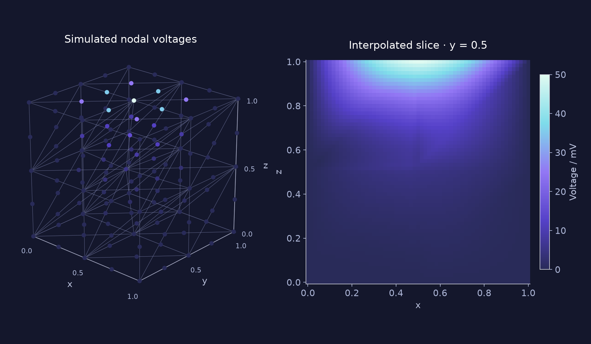
A discretization that fits the circuit
Programmable conductances set the weights in a network of connected circuit nodes. We develop numerical discretizations that use positive conductances and account for the circuit’s limited programming precision. Laplace’s equation provides a demanding elliptic test case for evaluating the approach.
Circuit error and discretization error
The circuit pilot uses 27 CMOS buffers and 1,080 generic stateful RRAM cells. Its final output differs from the programmed matrix solution by 0.0374%. Its interior nodal error against the continuum reference is 4.097%. These comparisons measure different things: how well the circuit solves its programmed equation, and how well that equation approximates the continuum problem.